Posted on
October 29, 2026
Pneumatic Control Systems for Rail Inflatable Seals: Valves, Regulation and Cycle Life
How the pneumatic control system behind a rail inflatable seal is built, what each component does, and where reliability problems usually start.
When an inflatable seal complaint arrives at a depot, the rubber tube is usually the first thing blamed and often not the thing at fault. The seal is only one half of a sealing system. The other half is the pneumatic circuit that inflates it, holds it and exhausts it on every door cycle, and its reliability decides how long the system performs.
This guide explains what the circuit has to do, what each component contributes, how a door cycle runs and where reliability problems usually begin. If you are new to the product itself, start with our introduction to what an inflatable seal is and how it works.
What the Control System Has to Do
The circuit has to deliver air to the seal at the right moment after the door closes, hold a regulated pressure for as long as the door is shut, release that air quickly before the door opens, and do all of this several hundred times a day for years. It also has to report its state to the door controller, so that the door does not move while the seal is still inflated.
The pressure matters because sealing force follows it. Too little and the seal does not bridge the gap, too much and the wall is over-stressed and fatigues early. Setting and holding that pressure is the job of the regulator, and it is one reason the supply pressure of the vehicle is never fed to the seal directly. Our article on pressure mistakes that cause inflatable seal bursts shows how common errors in this area lead to failure, and our guide to sizing an inflatable seal for gap, tolerance, stroke and pressure explains how working pressure relates to the gap.
The Components of a Typical Circuit
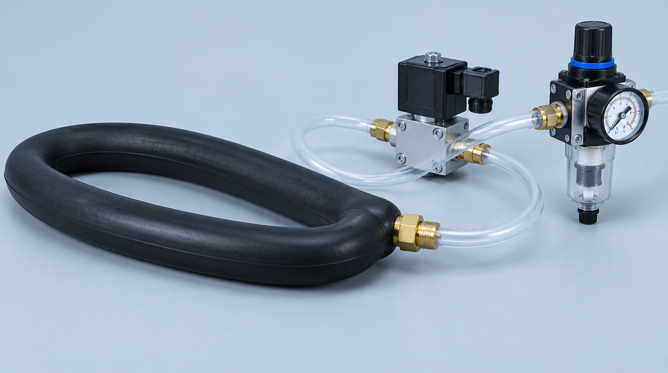
The layout varies between vehicles, but the building blocks are similar. The diagram below shows the path air takes, with the valves and the feedback sensor that control it.
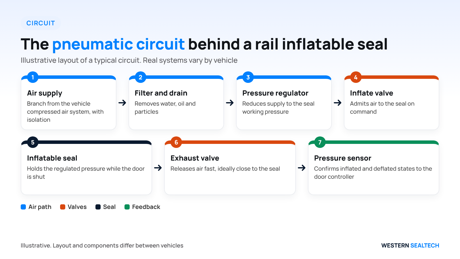
- Air supply - taken from the vehicle's compressed air system through a branch with isolation and filtration
- Filter and drain - removes water, oil and particles before they reach valves and the seal
- Pressure regulator - reduces the supply to the working pressure of the seal, which is typically much lower than the vehicle supply
- Inflate valve - a solenoid or pilot-operated valve that admits air to the seal on command
- Exhaust or quick-release valve - releases air from the seal fast, ideally located close to the seal so the tube does not have to push air back through long pipework
- Pressure switch or sensor - confirms that the seal has reached its inflated state and that it has fully deflated before the door moves
- Tubing, fittings and the end connector - the path between valves and the seal itself
| Component | Function | Common Reliability Concern |
|---|---|---|
| Filter and drain | Removes moisture and contamination | Blocked or neglected elements, wet air in cold weather |
| Regulator | Sets and holds working pressure | Drift or creep that raises or lowers seal force |
| Inflate valve | Admits air on command | Slow response, internal leakage |
| Exhaust valve | Vents the seal quickly | Sticking, slow venting that delays door opening |
| Pressure switch or sensor | Confirms inflated and deflated states | Incorrect setpoint, nuisance fault codes |
| Fittings and tubing | Carry air to the seal | Slow leaks at joints, chafing, kinks |
The tubing between the valves and the seal is part of the circuit too, and its material should suit the air quality, temperature and routing. Where flexible hose is used, our range of silicone tubing and hoses covers constructions for pneumatic and fluid service.
📊 Key point: Most reliability concerns in the circuit, such as wet air, regulator drift, slow valves and leaking fittings, show up as a seal complaint even though the rubber is not at fault.
The Door Sequence
A typical sequence runs as follows: the door reaches its closed and locked position, the controller commands the inflate valve open, air flows to the seal until the sensor confirms the working pressure, and the circuit holds that pressure while the vehicle is in service. When the door is about to open, the exhaust valve releases the air, the sensor confirms deflation, and only then does the door mechanism move. Some systems use a small vacuum to pull the tube fully back into its groove for extra clearance.
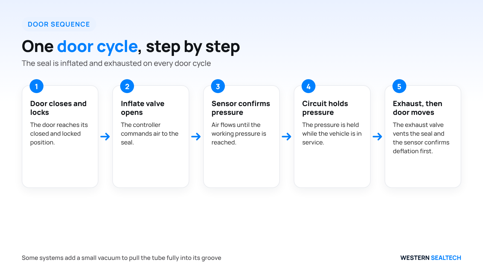
The order matters. If the door moves while the seal is still partly inflated, the seal can be dragged, pinched or cut. If the seal inflates before the door is fully locked, it can be loaded in a way it was never designed for. The sensor feedback and the interlock logic exist to prevent both.
The Interface With the Door Controller
The circuit does not work in isolation. The door controller decides when to inflate and when to exhaust, and it reads the pressure feedback to decide whether the door may move. Agreeing this interface early avoids a common source of trouble, where the sealing system and the door system are specified by different suppliers and no one owns the signal between them.
- Which signal commands inflation, and which commands exhaust
- What the controller does if the inflated state is not confirmed within a set time
- What the controller does if deflation is not confirmed before the door is commanded to open
- How fault codes are raised, and how they are cleared after maintenance
📌 Note: Whatever the logic is, it should be written down and shared with the supplier of the seal and the valves, so that tolerances, delays and fault thresholds are consistent.
Air Quality and Cold Weather
Compressed air on a vehicle is rarely perfectly dry. Moisture, oil mist and fine particles reach the door branch unless they are removed, and they cause trouble in a predictable order: valves stick or leak, regulators drift, and in cold weather condensed water can freeze in the lines. A seal that is inflated by a partly frozen circuit may inflate slowly, hold less pressure than intended or fail to exhaust.
Filtration and drainage should therefore be treated as part of the sealing system, with a maintenance interval that matches the vehicle's operating conditions. It is also worth asking how the circuit behaves at the cold end of the climate range, because a design that works in a workshop can behave differently on a winter morning.
Design Points That Decide Reliability
A handful of design decisions account for much of what goes wrong later. The cards below summarise four of them, and the list gives the detail.
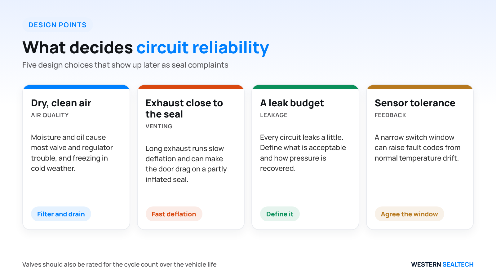
- Dry, clean air. Moisture and oil are the most common causes of valve and regulator trouble and, in cold weather, of freezing in the lines
- Exhaust close to the seal. Long exhaust runs slow deflation and can cause the door to drag on a partly inflated seal
- A leak budget. Every circuit leaks a little. The design should define how much leakage is acceptable and how the system recovers pressure, so that a minor leak does not cause constant compressor cycling across a fleet
- Sensor tolerance. A pressure switch with a narrow window can trigger fault codes from normal temperature drift
- Valve duty rating. Valves must be rated for the cycle count over the vehicle life, not only for a short bench test
⚠️ Watch out: A pressure switch with a narrow window can trigger nuisance fault codes from normal temperature drift, so agree the sensor tolerance with the door controller supplier.
How Circuit Faults Show Up as Seal Complaints
Because the seal is the visible part of the system, circuit faults are often reported as seal faults. A slow leak at a fitting gives the same symptom as a pinhole in the tube. A sticking exhaust valve looks like a seal that will not retract. A drifting regulator looks like a seal that sometimes seals and sometimes does not.
The way to separate the two is to work from the air supply toward the seal, rather than starting with the rubber. Our step-by-step guide to diagnosing an inflatable door seal that is losing pressure sets out that sequence, and our article on inflatable seal failure modes on rolling stock shows what real seal damage looks like once the circuit has been ruled out. For a wider view of why seals fail early, see our piece on why inflatable seals fail early.
Choosing the Seal and the Circuit Together
The seal profile and the control circuit influence each other. A profile with a large internal volume takes longer to inflate and exhaust, which affects the valve and pipework size. A section with a small retract clearance needs reliable, complete deflation, which puts more weight on the exhaust valve and the sensor. Our guide to inflatable seal profiles for rail doors covers the profile side, and the comparison of inflatable and static door seals is a useful check on whether an inflatable system is justified on a given door. Our inflatable seals product page describes the range we supply.
What to Share With a Supplier
For an RFQ that includes the control system, supply the vehicle air supply pressure range, the available packaging space near the door, the signal and interlock requirements from the door controller, the expected cycles per day, the climate range, and any existing circuit diagram.

💡 Tip: If the control system is in scope, send a circuit diagram as well as the door drawing, so valve and exhaust positions can be reviewed together with the seal.
For rail projects, our rail and mass transit sealing page describes the fire-safe sealing we supply, and our wider inflatable seals design guide covers retention, sizing and installation.
Key Takeaways
The pneumatic circuit is half of an inflatable sealing system. It must supply clean, dry, regulated air, inflate and exhaust quickly, and confirm both states to the door controller on every cycle. Design for dry air, a nearby exhaust valve, an agreed leak budget, sensible sensor tolerance and valves rated for the full vehicle cycle life, and share the full circuit context with your supplier.
Planning an inflatable seal package with its control circuit? Share your air supply and door interface details and we will review it with you.
Need a custom sealing solution?
Talk to our engineers about inflatable seals, rubber diaphragms and custom extrusions built to your exact spec. We respond within one business day.
Frequently asked questions
Why does the seal pressure need to be regulated instead of using supply pressure directly?
Vehicle supply pressure is normally far higher than a seal wall is designed to carry. Regulation protects the tube and its reinforcement from over-stress and gives a repeatable sealing force.
Where should the exhaust valve be fitted?
As close to the seal as practical, so air leaves the tube without travelling through long pipework, which keeps deflation fast and consistent.
Can a slow leak in the circuit be mistaken for a seal fault?
Yes. A leak at a fitting or valve gives the same symptom as a leaking tube, which is why a diagnosis should start at the supply and work toward the seal.
How many cycles should the control system be rated for?
At least the number of door cycles over the design life of the vehicle, with margin. Cycle counts on high-frequency metro doors can reach very high figures over the life of a fleet.
Is a vacuum assist needed to retract an inflatable seal?
Not in every system. It is used where retract clearance is very small or where the tube must be held reliably out of the door path.
Why do circuits sometimes misbehave in cold weather?
Moisture in the compressed air can condense and freeze in valves and lines, which slows inflation or prevents exhaust. Good filtration and drainage, and a check of behaviour at the cold end of the climate range, reduce the risk.
Who should agree the signals between the seal system and the door controller?
The door controller supplier, the valve supplier and the seal supplier should agree them together, including delays, fault thresholds and what the door does when a state is not confirmed.

Need a quote?
For custom rubber sealing solutions contact us. We will respond to you within 1 business day